Introduction/Additional information:
This message should be sent by base stations only, to inform about the status of different light signals to all vessels in a certain area. The information should be displayed on an external Inland ECDIS display as dynamic symbols. The message should be sent with binary message 8 at regular intervals
Details:
| Parameter |
Bit |
Description |
| Message ID |
6 |
Identifier for Message 8; always 8 |
| Repeat Indicator |
2 |
Used by the repeater to indicate how many times a message has been repeated. Default = 0
3 = do not repeat any more |
| Source ID |
30 |
MMSI number |
| Spare |
2 |
Not used, should be set to zero. Reserved for future use. |
| Application Identifier |
16 |
DAC=200, FI=40 |
| Signal position longitude |
28 |
Longitude in 1/10 000 min (±180 degrees, East = positive, West = negative. 181 degrees (6791AC0 hex) = not available = default) |
| Signal position latitude |
27 |
Latitude in 1/10 000 min (±90 degrees, North = positive, South = negative, 91 degrees (3412140 hex) = not available = default) |
| Signal form |
4 |
0,15 = unknown = default, 1-14 signal form according to ANNEX C: EXAMPLE OF SIGNAL STATUS |
| Orientation of signal |
9 |
Degrees (0-359) (511 indicates not available = default). |
| Direction of impact |
3 |
1 = upstream, 2 = downstream, 3 = to the left bank, 4 = to the right bank, 0 = unknown = default, rest not used |
| Light status |
30 |
Status (1 to 7) of up to 9 lights (light 1 to light 9 from left to right, 100000000 means colour 1 at light 1) per signal according to ANNEX C: example of signal status. 000000000 = default, 777777777 maximum, rest not used |
| Spare |
11 |
Not used, should be set to zero. Reserved for future use. |
| 168 |
occupies 1 slot |
ANNEX C: Example of signal status
C.1: Light status
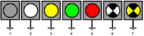
The examples show a grey background in a square of a fixed size of about 3 mm x 3 mm at all display scales with a “post” like it is used for the present static signal in the presentation library. The white point in the centre of the post indicates the position and the post itself allows the user to read the direction of impact. (At a lock, for example, there are often signals for vessels leaving the lock chamber and vessels entering the lock chamber on the inner and the outer side of the door construction) However, the manufacturer of the display software can design the shape of the symbol and the background colour.
The status of a signal can be “No light”, “white”, “yellow”, “green”, “red”, “white flashing” and “yellow flashing” according to CEVNI.
C.2: Signal forms
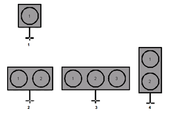
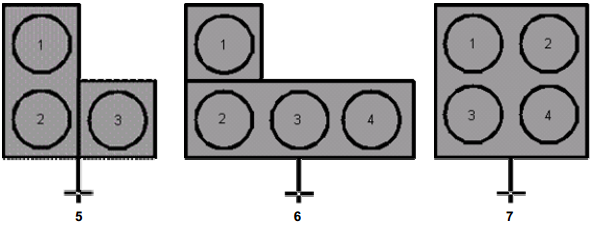
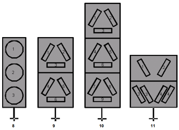

For each of these signals there are a lot of possible combinations of lights. It is required to use A number to indicate the kind of signal and A number for each light on a signal to indicate its status
1 = no light,
2 = white,
3 = yellow
4 = green,
5 = red,
6 = white flashing and
7 = yellow flashing.