Uploads by Oferiks
Jump to navigation
Jump to search
This special page shows all uploaded files.
| Date | Name | Thumbnail | Size | Description | Versions |
|---|---|---|---|---|---|
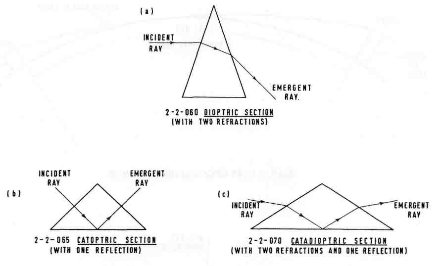
| 20:01, 28 February 2009 | Ch2 Fig31.jpg (file) |  |
17 KB | 2-3-220 BUNCH FILAMENT | 1 |
| 20:00, 28 February 2009 | Ch2 Fig30.jpg (file) |  |
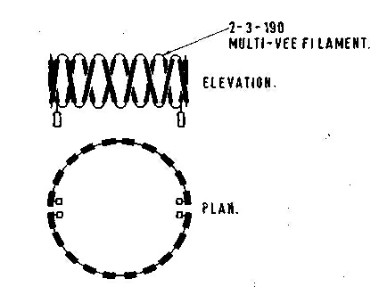
17 KB | 2-3-215 No English term | 1 |
| 20:00, 28 February 2009 | Ch2 Fig29.jpg (file) |  |
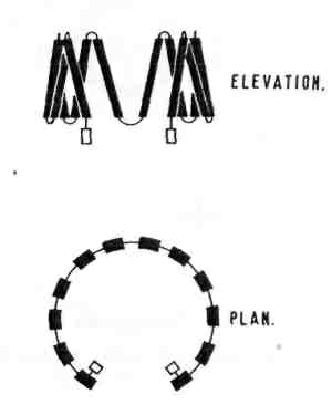
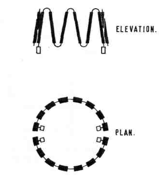
29 KB | 2-3-210 CYLINDRICAL FILAMENT (in this case the cylinder is closed in plan) | 1 |
| 19:59, 28 February 2009 | Ch2 Fig28.jpg (file) |  |
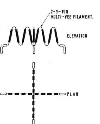
20 KB | 2-3-205 CRUCIFORM FILAMENT | 1 |
| 19:59, 28 February 2009 | Ch2 Fig27.jpg (file) |  |
53 KB | Illustrating 2-3-200 LIGHT-CENTRE-LENGTH of an INCANDESCENT ELECTRIC LAMP 2-3-080 | 1 |
| 19:57, 28 February 2009 | Ch2 Fig26.jpg (file) |  |
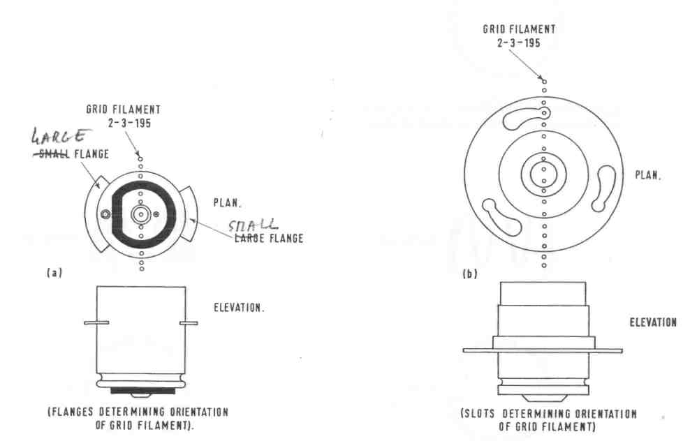
68 KB | 2-3-130 PRE-FOCUS CAPS | 1 |
| 19:56, 28 February 2009 | Ch2 Fig25.jpg (file) |  |
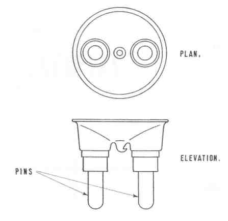
26 KB | 2-3-125 PIN CAP in this case illustrating a "bi-post" lamp (U.S.A.) 2-3-125 N | 1 |
| 19:55, 28 February 2009 | Ch2 Fig24.jpg (file) |  |
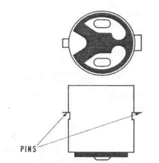
15 KB | 2-3-120 BAYONET CAP | 1 |
| 19:55, 28 February 2009 | Ch2 Fig23.jpg (file) |  |
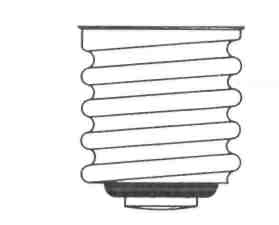
12 KB | 2-3-115 SCREW CAP EDISON SCREW | 1 |
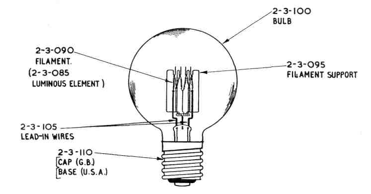
| 19:54, 28 February 2009 | Ch2 Fig22.jpg (file) |  |
47 KB | 2-3-080 INCANDESCENT (ELECTRIC) LAMP | 1 |
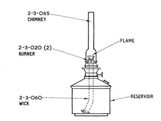
| 19:54, 28 February 2009 | Ch2 Fig21.jpg (file) |  |
28 KB | 2-3-055 OIL LAMP | 1 |
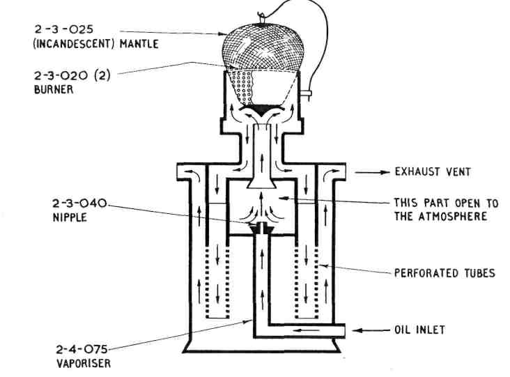
| 19:53, 28 February 2009 | Ch2 Fig20.jpg (file) |  |
73 KB | 2-3-035 PARAFFIN VAPOUR LAMP PARAFFIN VAPOUR BURNER | 1 |
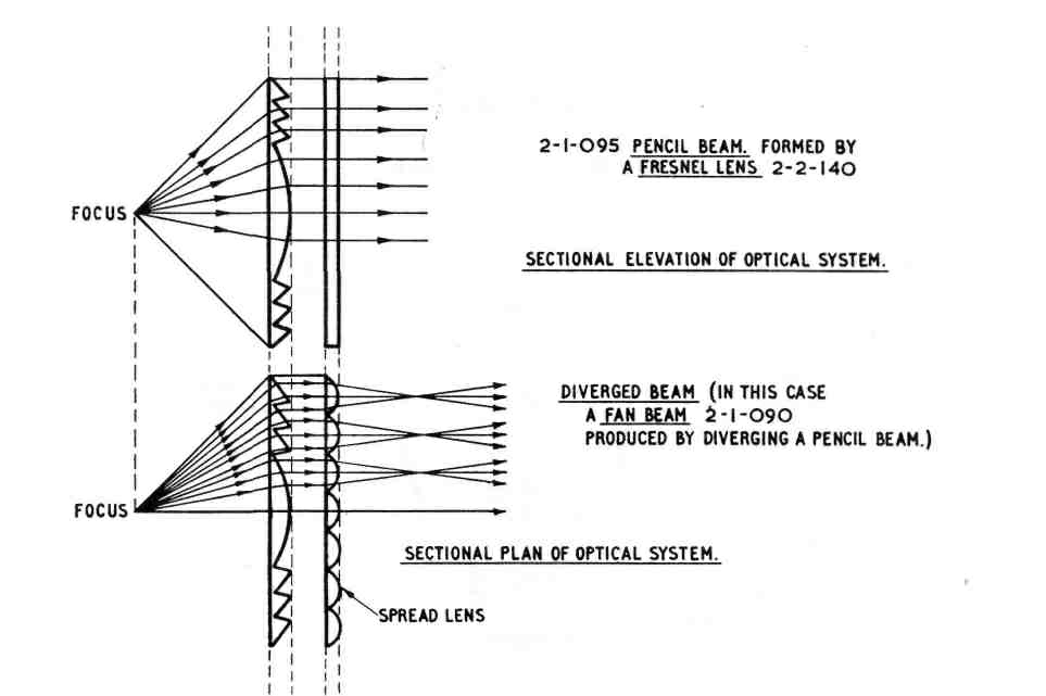
| 19:52, 28 February 2009 | Ch2 Fig19.jpg (file) |  |
93 KB | 2-2-220 DIVERGED BEAM | 1 |
| 19:52, 28 February 2009 | Ch2 Fig18.jpg (file) |  |
65 KB | 2-2-215 N DIRECTIONAL DRUM LENS illustrating the principle of a CONVERGED BEAM 2-2-215 ( in the absence of the converging prisms a 360° fan beam of nearly uniform intensity would be produced) | 1 |
| 19:50, 28 February 2009 | Ch2 Fig17.jpg (file) |  |
46 KB | 2-2-175 (OPTICAL PANEL) with a main beam and a DIVERTED BEAM 2-2-225 (in this example the diverted beam is for the use of aviation) | 1 |
| 19:48, 28 February 2009 | Ch2 Fig16b.jpg (file) |  |
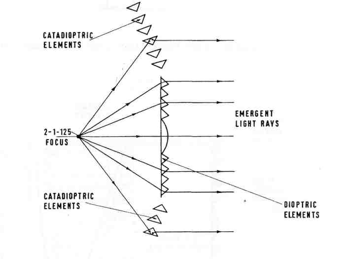
119 KB | -2-100 (DIOPTRIC) DRUM LENS (a type of fixed lens) | 1 |
| 19:47, 28 February 2009 | Ch2 Fig16a.jpg (file) |  |
50 KB | 2-2-090 FIXED LENS (in this case a Fresnel lens) | 1 |
| 19:47, 28 February 2009 | Ch2 Fig15.jpg (file) |  |
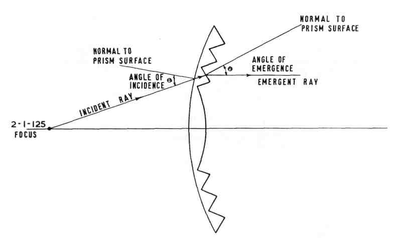
38 KB | 2-2-145 EQUI-ANGULAR PROFILE (showing equal angles of incidence and emergence) | 1 |
| 19:45, 28 February 2009 | Ch2 Fig14.jpg (file) |  |
47 KB | 2-2-135 FRESNEL PROFILE | 1 |
| 19:44, 28 February 2009 | Ch2 Fig13.jpg (file) |  |
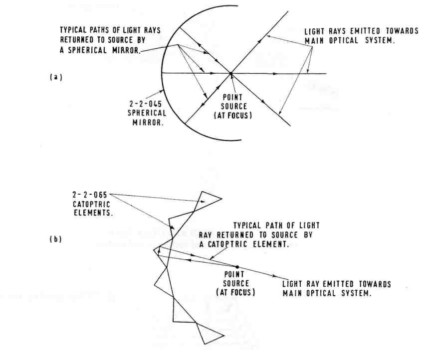
79 KB | 2-2-045 SPHERICAL REFLECTORS (used as REINFORCING MIRRORS 2-2-040) | 1 |
| 19:43, 28 February 2009 | Ch2 Fig12.jpg (file) |  |
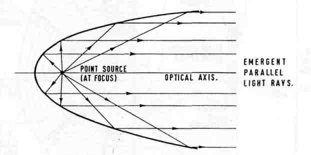
39 KB | 2-2-035 PARABOLIC REFLECTOR PARABOLIC MIRROR | 1 |
| 19:42, 28 February 2009 | Ch2 Fig11.jpg (file) |  |
60 KB | 2-2-020(1) PRISMATIC SECTIONS | 1 |
| 19:39, 28 February 2009 | Ch2 Fig10.jpg (file) |  |
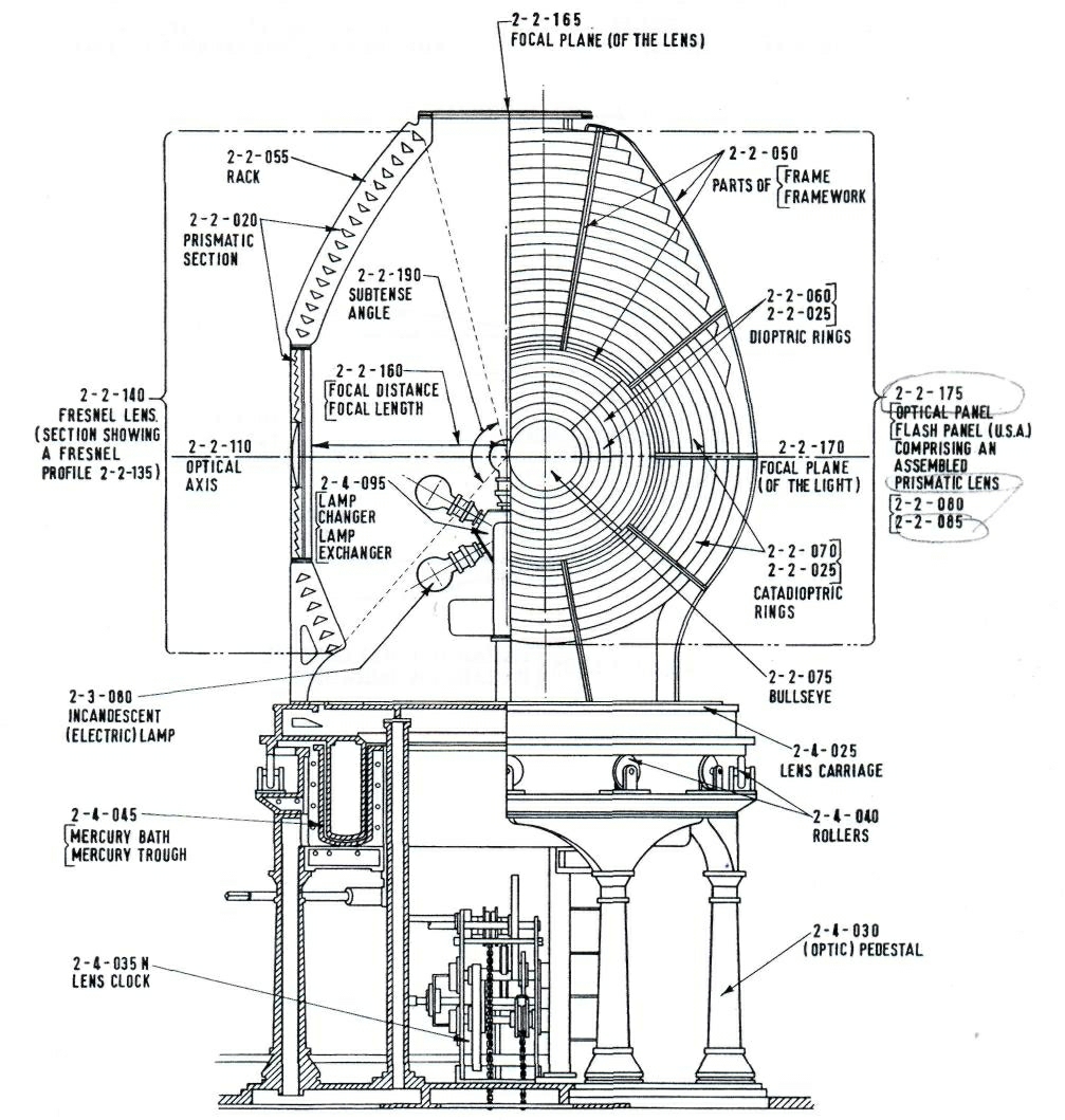
379 KB | 2-2-000 OPTIC with support and associated equipment | 1 |
| 19:39, 28 February 2009 | Ch2 Fig9.jpg (file) |  |
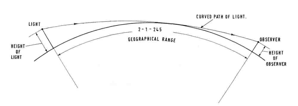
36 KB | 2-1-245 GEOGRAPHICAL RANGE | 1 |
| 19:38, 28 February 2009 | Ch2 Fig8.jpg (file) |  |
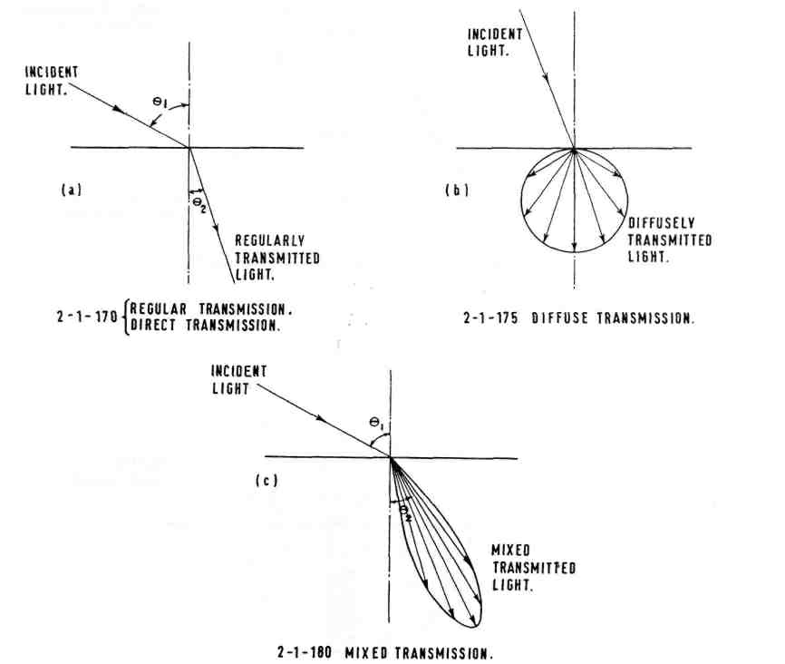
67 KB | TRANSMISSION. | 1 |
| 19:38, 28 February 2009 | Ch2 Fig7.jpg (file) |  |
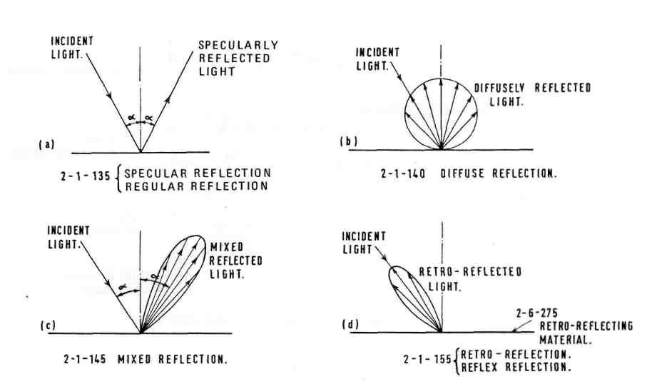
81 KB | REFLECTION. | 1 |
| 19:37, 28 February 2009 | Ch2 Fig6.jpg (file) |  |
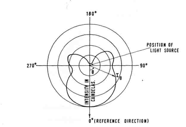
40 KB | 2-1-105 CURVE OF LUMINOUS INTENSITY DISTRIBUTION (of a light source) (in this case, in polar form) | 1 |
| 19:36, 28 February 2009 | Ch2 Fig5.jpg (file) |  |
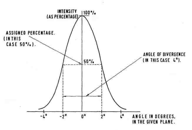
40 KB | 2-1-100 ANGLE OF DIVERGENCE. | 1 |
| 19:35, 28 February 2009 | Ch2 Fig4.jpg (file) |  |
44 KB | 2-1-065 INVERSE SQUARE LAW. | 1 |
| 19:35, 28 February 2009 | Ch2 Fig3.jpg (file) |  |
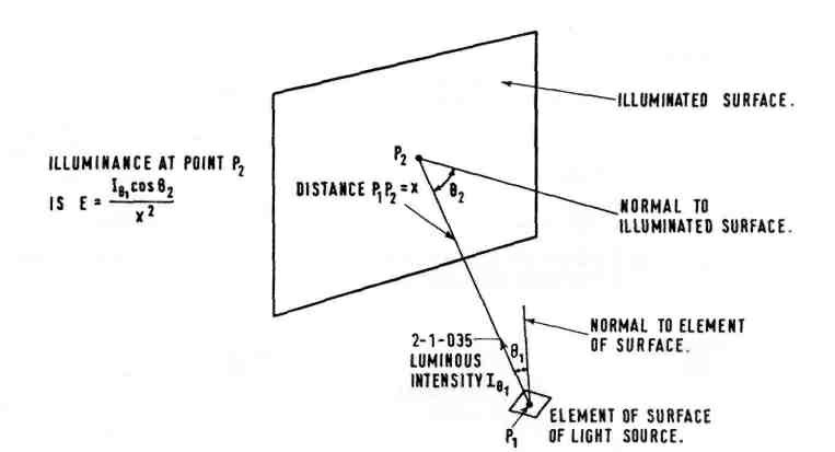
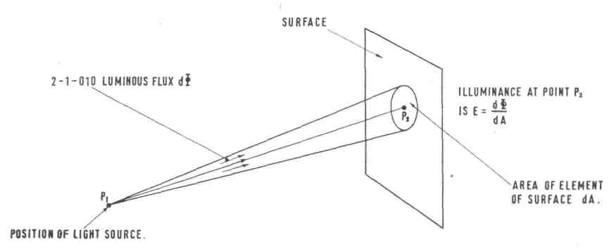
36 KB | 2-1-055 ILLUMINANCE (at a point of a surface). | 1 |
| 19:34, 28 February 2009 | Ch2 Fig2.jpg (file) |  |
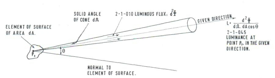
50 KB | 2-1-045 LUMINANCE (in a given direction, at a point on a surface). | 1 |
| 19:32, 28 February 2009 | Ch2 Fig1.jpg (file) |  |
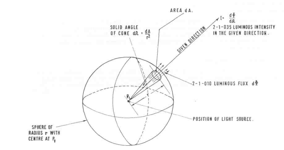
51 KB | 2-1-035 LUMINOUS INTENSITY (of a source, in a given direction). | 1 |
| 18:24, 28 February 2009 | Ch5 Fig3.jpg (file) |  |
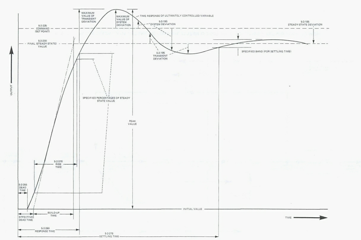
179 KB | Typical time response of a system to a step increase of input | 1 |
| 18:21, 28 February 2009 | Ch5 Fig2.jpg (file) |  |
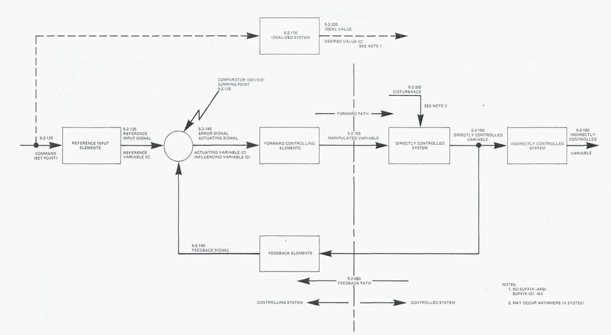
124 KB | Block diagram of automatic control system (5-2-045) incorporation a closed loop (5-2-080) | 1 |
| 18:17, 28 February 2009 | Ch5 Fig1.jpg (file) |  |
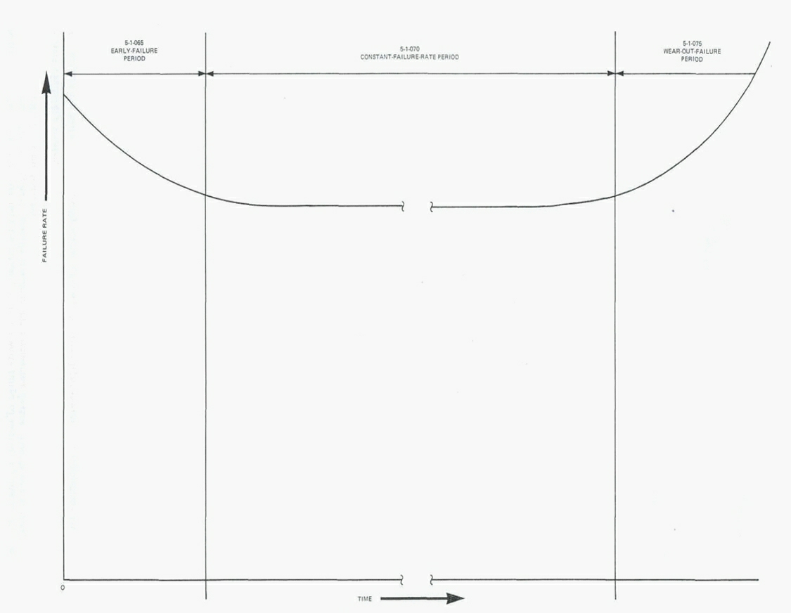
82 KB | Failure rate / Time pattern | 1 |
| 00:56, 13 February 2009 | 25px-Geographylogo.png (file) |  |
1 KB | Used for the Language bar at the bottom of each page | 1 |
| 00:41, 13 February 2009 | IALA Logo.jpg (file) | 9 KB | The Basic IALA Logo used on each page | 1 |