Predicting Collision Frequencies
Introduction
The conceptual procedure for calculation of the frequency of collisions or groundings follows the conceptual principles formulated by Fujii [7].
The procedure first involves the calculation of the geometric number of collision or grounding candidates, NG , which subsequently is multiplied by the causation factor, Pc. Hence the frequency of collisions, λcol , (or groundings, λGnd) become:
The theoretical procedure laid out in this chapter represent the state-of-the-art framework that is applied for calculating the geometric number of collision and grounding candidates, NG.
A prerequisite for the analysis is that the ship traffic has been grouped into a number of different ship classes according to vessel type, size, loaded or ballasted, with or without bulbous bow etc., and that the number of vessels per time unit have been registered for each waterway.
It is noted that in the analysis presented below the time unit for the definition of number of vessels is in seconds-1 for dimension correctness.
Collisions Types
Collisions may coarsely be divided into two types:
- collisions along the route segment, i.e. overtaking or head-on collisions, and
- collisions when two routes cross each other, merge, or intersect each other in a bend of a fairway.
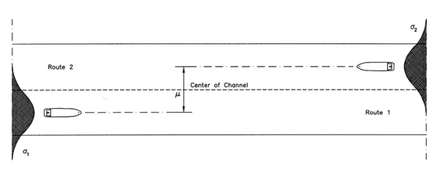
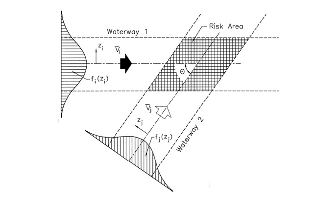
The procedure for calculation of the number of collision candidates, NG, for the above mentioned two types are conceptually different since the geometric number of collision candidates first type becomes dependent on the lateral traffic spread on the route whereas the second is independent of the traffic spread. This can be seen by comparing Figure 2 and Figure 3.
Figure 2 Definition of μ-ratio and traffic distribution.
By inspecting Figure 2 it can be seen that the probability of the path of two meeting ships will overlap depends on the spreading of the lateral position where the vessels are sailing.
The larger the μ -value the smaller becomes the probability of a collision.
Figure 3 Crossing waterways with risk area of ship-ship collision.
In Figure 3 it can be seen that although the “risk area” is affected by the spread of the traffic the probability of the ships meeting each other is not.
In the following, head-on and overtaking collisions will first be treated, thereafter crossing collisions.
Head-on and overtaking collisions
Collisions along the route, see Figure 2, depends on:
- The length, W L , of the segment;
- The traffic composition, i.e. the number of passages per time unit for each ship type and size, Qi(1)and Qj(2) , in each direction, (1) and (2), and their speed, Vi(1) and Vj(2) ;
- The geometrical probability distribution, fi(1)(y) and fj(2)(y), of the lateral traffic spread on the route. The traffic spread is typically defined by a Normal Distribution but may in principle be of any type.
The sign convention for the traffic distribution is measured from the centre of the channel and positive towards the right side in the sailing direction.
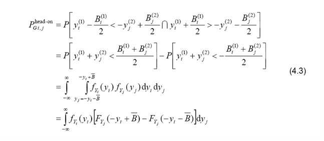
For head-on collisions the number of geometric collision candidates for ships sailing along the route segment in direction (1) and (2) can be expressed as,
where Vij = Vi(1) + Vj(2) is the relative speed between the vessels and PG defines the probability that two ships will collide in a head on meeting situation. This probability is expressed as:
It is noted that the random variable Yj(2) is negative because of the positive sign convention in the sailing direction of the two vessels. In the last step it has been utilized that the two distributions are independent. It is possible to establish a closed form solution to Eq. (4.3) when the traffic distributions are normally distributed. In the general case Eq. (4.3) must in be solved by approximate procedures such as FORM/SORM or numerical integration. When fi(1)(y) and fj(2)(y) both follow a normal distribution with distribution parameters (μi ,σi) and (μj ,σj), respectively, eq. (4.3) can be written as:
The frequency of head on collisions, λ head-on Col, is obtained by multiplying the geometric number of collisions, NG head-on, with the causation factor for head on collisions, PC head-on.
In the DROGDEN study a causation factor of 1.3⋅10−4 was applied for head-on and overtaking collisions. In the resent study “Oil and Chemical spills in Danish waters” [3] a factor of 3.0 ⋅10−4 was proposed. Based on collision statistics in Japanese waters, Fujii et al. [8] has estimated that for meeting ships in parallel waterways Pc = 4.9⋅10-5. For overtaking collisions the number of geometric collision candidates for ships sailing along the route segment in direction (1) is expressed by eq. (4.2) using the relative speed Vij = Vj(2) - Vj(2) , Vij > 0. If Vij < 0 then vessel i will obviously not be able to overtake vessel j. In the practical implementation the absolute value of Vij is used and struck and striking vessel are registered. The geometric probability of meeting, eq. (4.3) becomes,
For normally distributed variables the mean value in eq. (4.4) should be replaced by μij = μi(1) − μj(2) to handle the overtaking situation.
Crossing collisions
The frequency of crossing collisions depends on the angle between the two lanes. Figure 3 shows two crossing waterways for which the ship traffic also is given. The geometric number of crossing collision candidates for crossing waterways can similarly to eq. (4.2) be expressed as,
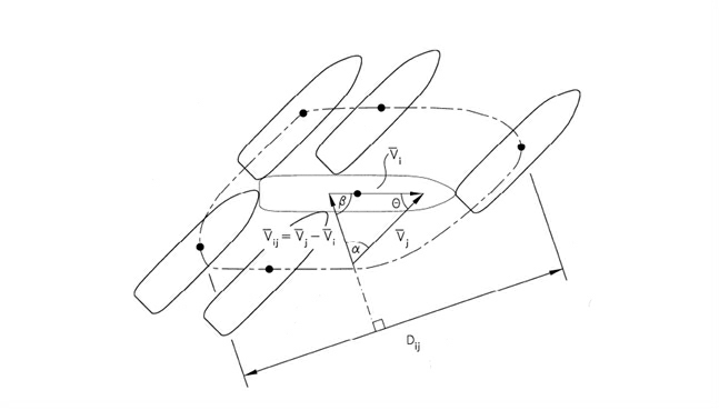
and Dij, defines the apparent collision diameter, see Figure 4. The sinus term stems from the variable transformation when integrating over the area of the joint probability distribution, see Figure 7. Note that contrary to head-on and overtaking collisions the distribution of the traffic spread is not relevant for crossing collisions, except for the sinus term of course. It is seen that when the crossing angle goes to zero the length of the crossing (or the time of the crossing) goes to infinity and hence does the number of collisions. For practical reasons it is therefore necessary to limit the crossing angle to an interval of, say, 10 to 170 degrees.
Figure 4 Definition of geometrical collision diameter Dij.
Figure 5 Calculation of the geometrical collision diameter Dij.
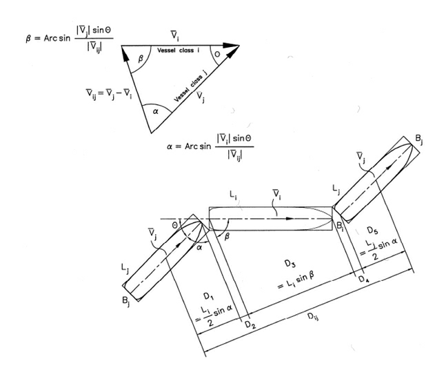
As mentioned Dij is the geometrical collision diameter illustrated in Figure 4. If it is assumed that the ships can be approximated by rectangular shapes, then it can be shown, see Figure 5, that:
where the relative velocity Vij is determined as
and where Bi is the width of ship i and Li the length.
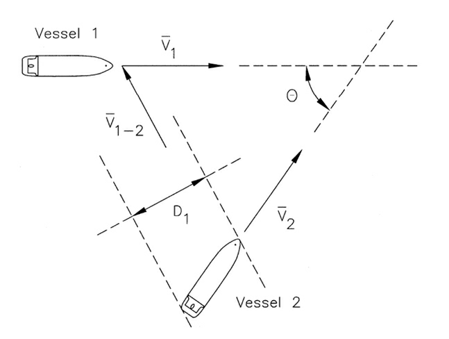
Figure 6 Illustration of the apparent diameter for vessel 1 striking vessel 2.
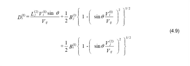
In the present work we are not only interested in the number of ship-ship collisions but also in the probability of the one or the other being the struck or striking vessel. To derive a simple expression for this event the apparent collision diameter is formulated, see Figure 6. The apparent collision diameter seen from vessel i , Di(1), can be determined as:
Similarly, for the case where vessel j in waterway 2 is striking vessel i in waterway 1 the apparent collision diameter is:
It is seen that the total collision diameter Dij is the sum of the two apparent collision diameters, i.e.:
The probability of vessel i in waterway 1 striking vessel j in waterway 2 given a collision may then be determined as:
Similarly, the probability of vessel j in waterway 2 striking vessel i in waterway 1 is found as
The frequency, λship−ship, of ship-ship collision per time unit is then determined as
Due to the fact that both of the involved two ships have the possibility of making aversive manoeuvres, the causation probability, Pc , for ship-ship collision is smaller than the one given for grounding and collision against fixed objects, see Section 5.1. Based on collision statistics in Japanese waters, Fujii et al. [8] estimated that for crossing ships Pc = 1.2⋅10-4 and for meeting ships in parallel waterways Pc = 4.9⋅10-5. Given the frequency of the (annual) number of collisions λship− ship the probability of having a collision during time interval Δt can be estimated on the assumption of arrivals of the collisions as points in a Poisson process:
Provided, of course, that the collision frequency of is time invariant.
Area Collision
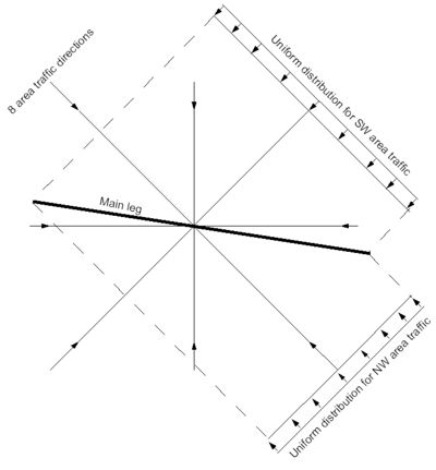
To account for traffic not following the defined legs, area collision calculation is carried out. Area traffic sails randomly. To model this, 8 area traffic legs are defined for each main leg. These 8 area traffic legs then intersects the main leg. The directions are N, NE, E, SE,S,SW,W and NW. Depending on how the legs intersects the main leg, either crossing or head-on collision is calculated. The lateral distribution of the area traffic is uniform, and the lower and upper boundary is such that the area traffic can intersect the main leg in its entire length. In case of head-on collision the lower and upper bound is set according to the main leg's lateral distribution. The number of area ships are given by the user as an intensity [ships crossing the main legs pr. year].
Omar (20100311): Sizes of ships are 25m and/or 50m length (Erik to check with Per Engberg exactly what lengths are used)?
Sensitivity Analysis
In order to verify the established analytical model and at the same time gain insight in the sensitivity of the number of collision candidates with respect to parameters such as crossing angles θ , ship dimensions, and ship speeds a program has been written which is based on time simulation.
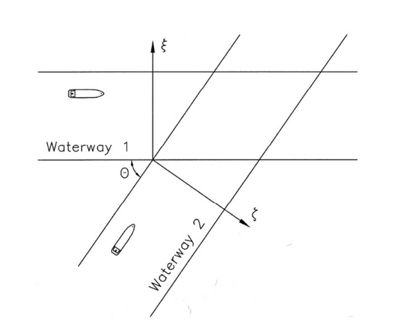
Figure 7 Basic layout of the simulated crossings with results presented in Figure 8 and Figure 9.
What has been considered is vessels of the same type in waterway 1 crossing the axis ξ, see Figure 7, as points in a Poisson process with intensity Q1 = 20000 vessels per year. The vessels in waterway 1 are assumed normally distributed over the width of the channel with μ = 100 m and σ = 45 m. Similar assumptions are made for vessels in waterway 2 crossing the axis ζ in Figure 7. Here Q2 = 50000 vessels per year and μ = 100 m and σ = 45 m. The vessels in the two waterways are moving with speed V1 and V2, respectively.
A time history of +/- one hour of simulated vessels in waterway 1 is kept for matching against simulated vessels in waterway 2, i.e.
t1 - 3600s < t2 < 3600s + t1.
During the simulation it is calculated whether or not the two vessels are colliding. If they are observed to collide, it is further identified which of the vessels is the struck vessel and which is the striking vessel.
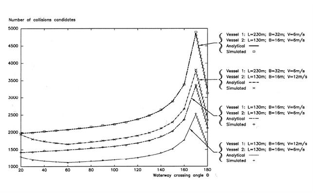
Figure 8 Comparison between simulated results assuming a Poisson distribution of ships in the two waterways and analytical results using Eq. (4.6)
Figure 8 shows the number of collision candidates during a period of forty years determined by time simulation and determined by the analytical expression Eq. (4.6) as functions of the angle θ between the two waterways.
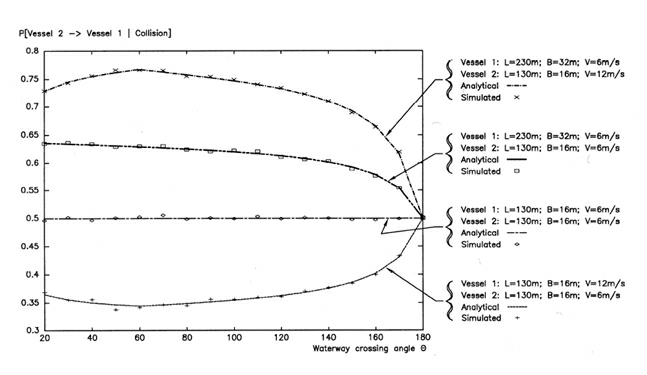
Figure 9 Simulated and analytical results for the probability of vessel 2 colliding with vessel 1 given a collision.
|
Source: IWRAP Mk II, Basic Modelling Principles for Prediction of Collision and Grounding Frequencies, (draft working document), Rev. 4, 2008.03.09, Peter Friis-Hansen, Technical University of Denmark. |

