Predicting Grounding Frequencies
Types of Grounding Scenarios
Following Pedersen [25], the grounding scenarios may broadly be divided into four main categories:
| Category | Grounding Scenarios |
|---|---|
| I. | Ships following the ordinary direct route at normal speed. Accidents in this category are mainly due to human error, but may include ships subject to unexpected problems with the propulsion/steering system that occur in the vicinity of the fixed marine structure or the ground. |
| II. | Ships that failed to change course at a given turning point near the obstacle. |
| III. | Ships taking evasive actions near the obstacle and consequently run aground or collide with the object. |
| IV. | All other track patterns than Cat. I, II and III, for example ships completely out of course due to loss of propulsion. |
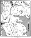
Figure 10 Observed grounding events over a 15-year-period in a Danish Strait, from [25].
It can be seen that most of the grounding events belong to category I and II, but there are also category III and IV groundings which seem to be randomly scattered over the area.
In formulating a theoretical model for the grounding scenario it is expedient to divide the grounding scenario into powered groundings and drifting groundings. Such division eases not only the frequency assessment but also the pursuing consequence assessment. In the following, expressions are presented for predicting the expected annual number of grounding events of category I and II accidents. The probability of category III and IV grounding events are today normally found by modification of the traffic distribution along the route.
In the present work drifting ships (category IV) are modelled by assuming a drifting direction according to a user specified wind rose. Evasive manoeuvres (category III) are not explicitly dealt with in the present version. We revert to these issues later.
Lateral Traffic Distribution
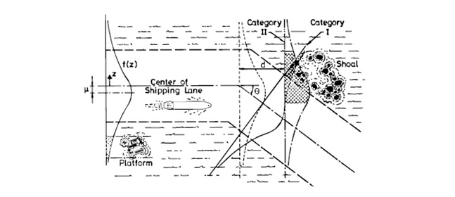
Ships in category I and II, following an ordinary route, are distributed over a transverse section of the waterway (Lateral Traffic Distribution) with some probability density function, fi(z) , where index i refers to a ship class and z is the transverse coordinate, see Figure 11:
Figure 11 Illustration of model for predicting the expected number of grounding events or collisions with fixed objects on a given ship route, from [25].
The shape of fi is a strong function of the considered waterway so a major challenge of the present approach is to define rationally fi(z) along a given route. Given fi the number of candidates of grounding events can be calculated as an integral of fi over the width, zmin to zmax , of the obstacle.
The hatched area in Figure 11 illustrates this. Most of these candidates will be aware of the danger and take the necessary aversive actions before they hit the obstacle. However, a fraction, Pc , of the candidates will fail to avoid the obstacle, due to for example human and technical errors. The fraction Pc is normally referred to as the Causation Probability, and it will be shown later how it can be estimated.
Groundings that are caused by a meeting situations where ships may feel forced to give way, which then subsequent may result in grounding, has not been considered. Such a model requires much more advanced modelling than what is implemented at the present stage. Neither have groundings that are caused by a “rudder stuck” failure. In this case the rudder may either go the extreme starboard/port side or it will get stuck in a central position and cause the vessel either to turn in circles or to follow its path.
Powered Grounding
According to the model described above, the expected number of grounding events in Category I and II can be calculated as:
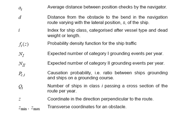
where the following notation has been used:
In the above it is assumed that the event of checking the position of the ship can be described as a Poisson process. Thus, the factor exp(−d/ai ) represents the probability of the navigator not checking the position from the bend to the obstacle.
The average distance between position checks is conveniently expressed in terms of the expected value of the time between position checks, λ, (approximately equal to 3 minutes or 180 seconds) whereby the factor exp(−d/ai ) becomes a function of the ship speed, ai = λ V. Eq. (4.16) is only correct for the case when the ground is orthogonal to the sailing route, which rarely is the case. In the event of the ground not being perpendicular to the sailing direction, but inclined so that the distance d from the bend to the ground may be expressed as d = az + b. In the event that the two traffic spread distributions follow a normal distribution then Eq. (4.16) can be simplified to:
For other type of distributions, especially for mixed distributions, it is not a straight forward task to formulate a closed form solution to the number of grounding candidates. For such distributions the integral can be effectively solved by solving part of the integral analytical and then performing a numerical integration over the remaining variables.
With the formulation above the expected number of annual grounding events becomes a function of traffic distributions, bottom topology, route layout etc. It is seen from Eq. (4.15), (4.16) and (4.17) that another important parameter is the causation factor, Pc , determining how large a fraction of the accident candidates actually run aground or hit the obstacle. Chapter 5 gives a thorough presentation of the causation factor. Often the causation probability is selected to be in the vicinity to Pc = 2 ⋅10−4.
The calculated expected number of yearly (powered) grounding events, Ng = NI + NII, can be considered as the intensity in a Poisson process. The probability of no grounding events in one year is then:
Drifting Grounding
The probability of category III (evasive manoeuvres) and category IV (drifting ships) grounding events are today typically found by modification of the traffic distribution along the route. Combining a 98% Gaussian distribution and a 2% uniform distribution performs the modification of the traffic distribution; see e.g. Gluver and Olsen [12] or Karlson et al. [19].
The value of 2% is based on engineering judgement and the results are dependent on the value especially in narrow restricted waters. Although this approach is very fast and easy to implement, it is considered to be too coarse a model that does not properly account for the physical effects that governs the drifting problem. In the section the implemented drifting model is defined.
The two main causes for a ship to be not under command are rudder stuck and blackout of the main engine. Rudder stuck will not be dealt with in this study. Most ships experiences of the order of one black out of the main engine per year. The number of any blackout for a given ship will typically lie in the interval from 0.1 to 2 blackouts per year.
The actual frequency of blackouts depends on the degree of redundancy and the general maintenance level of the ships. Ferries and ro/ro vessels generally have a high degree of built-in redundancy into the engine room (2 to 4 propulsion units) and hence they have a low frequency of blackouts. For many other single propulsion unit ships the frequency of blackouts are higher.
In the present study the following blackout frequencies are selected as base values:
A blackout may be caused by contaminated fuel, internal fault in the main engine, or failure of the electrical system. The seriousness of the incident depends on the location at which the blackout occurs, the wind direction, wind speed, and of course the duration of the blackout (that is the drifting time).
If a high degree of redundancy has been built into the engine room then the command over vessel may be regained in relative short time. In other situations, the drifting time may be of order of hours. The drifting ship will drift side ways and it will drift (approximately) in the direction of the wind.
The drifting scenario may be remediable either by repairing the problem, by anchoring the vessel or by calling a tug boat. Failure of propulsion machinery may occur at any location along the waterway. Assuming that blackouts occur as points in a Poisson process then the probability of having a blackout along a leg segment of length Lsegment is:
In which blackout λ is the frequency of blackout and vessel v is the operational speed of the vessel. The number of drifting groundings, Ndrift grounding , out of the Nship candidates of a particular ship type and size, can be calculated as:
In which Pwind(ψ) defines the probability of having wind coming from direction ψ.
The probability of no repair is defined by the complementary distribution function of the repair time distribution. The default repair time distribution is modelled as a Weibull distribution,
with scale parameter a = 1.05 and shape parameter b = 0.9 , which gives a mean value of 1 hour and standard deviation of 1.13 hour.
The distribution for the repair time has not been justified by data, but is defined based on an engineering assessment in discussion with two experienced first engineers having several years of operational experience. The distribution function is shown in the figure below.
The time to grounding is defined as ground tground = dground/vdrift, in which vdrift is the (uncertain) drifting speed and d(ground(x) defines the distance from the leg segment to the ground. The drifting speed is defined through its probability density function f(vdrift), which possibly may be defined as a function of the wind speed and the vessel type (at present this is not implemented in IWRAP). At present the drifting speed is assumed to be uniformly distributed in the interval [1 m/s; 3 m/s]. The conditional vector Z = {x,ψ,v} defines the parameters on which the time to grounding is conditioned.
Depending on the area and the vessel drifting speed of the, the captain may decide to drop the anchor to avoid the vessel is drifting on ground. At present the probability of no anchoring is set to 1. In future when more information has been gathered this model will be revised.
Calculating Total Number of Groundings
The total number of groundings from all grounding categories is calculated as:
|
Source: IWRAP Mk II, Basic Modelling Principles for Prediction of Collision and Grounding Frequencies, (draft working document), Rev. 4, 2008.03.09, Peter Friis-Hansen, Technical University of Denmark. |


