The testbed is located at Thales Italia premises in FIRENZE, Italy.
Functional Capabilities
The testbed verifies the functionality of the Terrestrial VDES link.
We have also developed an additional interface, allowing the following functions:
– Shore’s VDES can send to Ship’s VDES the Weather condition forecasts for the specific ship’s AIS position
– Ship’s VDES can transmit a mayday signal to Shore’s VDES, together with additional information (evacuation status, n. of passengers, n. of injured people, etc.) when received by the Ship’s ICT.
Intended Purpose (including benefits)
The purpose of the testbed is to verify the VDES prototype functionality and its interaction with the Palaemon Core platform in order to improve ship mass evacuation procedures and facilitate search and rescue operations.
Our objective is also to further develop the VDES prototype in order to arrive at a commercial product.
Portrayal examples (means or methods of portrayal)
The testbed consists of two VDES prototypes acting like a VDES_Ship and a VDES_Shore, connected through a radio link. A third VDES node provides the AIS signal to the platform.
PALAEMON Project
1. Introduction
VHF Data Exchange System (VDES) is a radio communication system, defined by IALA Guidelines [4], [5] and ITU-R Recommendation [1], that operates between ships, shore stations and satellites. VDES features an efficient use of radio spectrum, building on the capabilities of AIS (Automatic Identification System), used for vessel tracking and other navigational and safety-related purposes, and addressing the increasing requirements for data through the system. New techniques providing higher data rates than those used for AIS is a core element of VDES. Furthermore, VDES network protocol is optimized for data communication so that each VDES message is transmitted with a high confidence of reception [2]. Thales Italia (a Thales Group company) has developed a VDES prototype in the frame of the EU-funded Project « Palaemon » [3]. Palaemon is a holistic passenger ship evacuation and rescue ecosystem, which scope is providing a Proof-of-Concept (PoC) of an innovative Situational Awareness and Decision Support System to improve ship mass evacuation procedures in response to maritime incidents, by designing an innovative Mass Evacuation Vessel (MEV) and developing a Smart Evacuation Management System. In this project, Thales Italia has also defined an Authentication and Encryption mechanism established between the software modules of the Palaemon platform. The following Chapters describe how VDES can rely on such Authentication and Encryption architecture to securely access and exchange the relevant information.
2. OVERVIEW OF PALAEMON PLATFORM
In more detail, the Palaemon system implements and integrates a number of ICT methods and tools (coupled with the required hardware infrastructure) that can be summarized as follows: • A number of Data Sources, that collect information about ship stability and health status, weather forecast information, passengers real time positioning, etc. • A Core Platform, composed by specific software modules that elaborate the data inputs and store the relevant information in a central Data Base. • Several System Outputs, that receive and present the outcomes of the Core platform modules, e.g.: information is presented on the integrated bridge to support the Ship Master in deciding about evacuation; in case of evacuation, information is sent to the crew to easily locate and evacuate passengers; evacuation notifications are sent directly to passengers; other information is sent, via VDES, to shore stations or other ships to help search and rescue operations, etc.
4. VDES IMPLEMENTED ARCHITECTURE
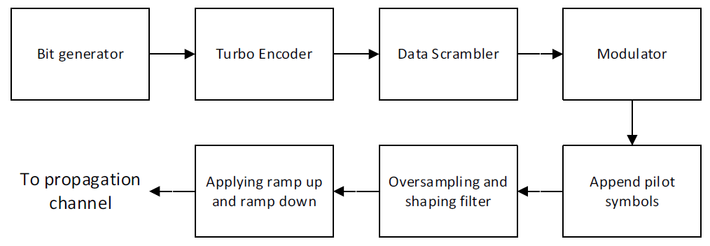
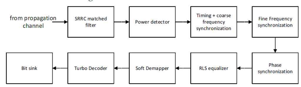
For the implementation of the VDES prototype in the context of the Palaemon project, the Software Defined Radio (SDR) technology has been adopted. The following figures show the VDE transmitter architecture, implemented in the simulator, used for performance assessment, and the receiver section architecture:
For the software implementation of the Waveform, developed in C++ language, the basic idea has been to map a single algorithm over a thread. The resulting software architecture is that of multi-threads working in pipeline. The concept above relies on the mechanism of data exchange among two consecutive threads. The shared buffer has been implemented with read and write methods, used by “consumer” and “producer” threads, regulated by a mechanism, which checks the validity of the data read / written. The resulting software architecture of the multi-thread framework consists of the following elements: shared buffers; chain of transmission threads; chain of receiving threads; global variables; variables shared across multiple threads.
4. VDES SDR Hardware solution
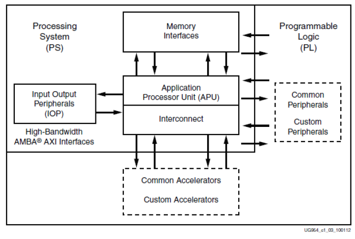
As SDR hardware platform, a combination of radio and carrier boards has been selected, able to carry out the development of an optimised high performance SDR solution, whilst retaining the flexibility to support specific OEM/ODM needs and future evolution of the standard. This architecture consists of a Base-Band (BB) System-on-Chip (SoC), paired with Radio Frequency (RF) SoC, in particular we have selected: • Analog Device EVAL-ADRV9002 evaluation board, as radio front-end • Xilinx Zynq®-7000 SoC ZC706 Evaluation Kit, as carrier board The BB SoC contains Field Programmable Gate Array (FPGA) fabric and ARM dual-core Cortex A9 processor. Its high-level block diagram is shown in the following figure:
Figure 3 Zynq 7000 High level block diagram
The selected RF card operates from 30 MHz to 6000 MHz and covers the UHF, VHF, licensed and unlicensed cellular bands, and industrial, scientific, and medical (ISM) bands. This board can support both narrowband and wideband standards up to 40 MHz bandwidth on both receive and transmit. The ported VDES transceiver code has been adapted, with respect to the VDES simulator code, in order to interface the RF front end section of the selected hardware platform. This interface relies on the C APIs, to initialize, configure, program, and control the RF front end both in transmission and reception.
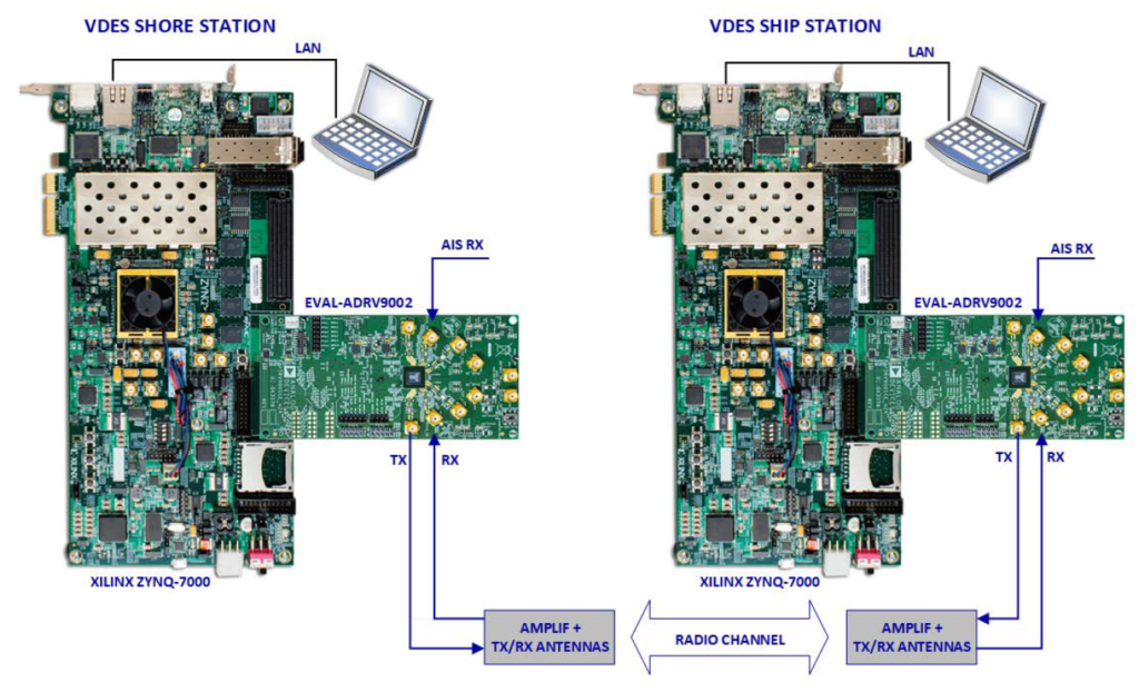
Figure 4 Overall VDES prototypes setup
The two boards have been assembled and connected to amplifiers and antennas in order to create a VDES prototype. In order to perform validation tests, between two VDES prototypes a Radio Frequency link has been established. The overall test setup is shown in Figure 4.
5. VDES OPERATION IN THE PALAEMON ECOSYSTEM
In normal operation, VDES will feed Palaemon platform with data from coastal stations or other vessels, e.g., weather or environmental conditions, position monitoring, etc. At the same time, the VDES software is subscribed to the notifications from a Palaemon software module called Evacuation Coordinator, allowing it to be aware of evacuation phase changes. In case of evacuation, ship’s VDES transceiver can broadcast a Mayday signal and send messages to coastal stations and vessels, e.g. the evacuation plan, passenger list, ship waypoints and route plan report, useful for Search & Rescue operations. In order to interface the VDES radio with the Palaemon platform, we have developed an application, called VDES Gateway (VDES_GW), using RUST programming language [12]. Two versions of VDES_GW have been deployed: one for Ship side and one for Shore side.
We have demonstrated the VDES end-to-end functionality in three use cases: 1) AIS position extraction 2) Weather information acquisition 3) Evacuation information transmission
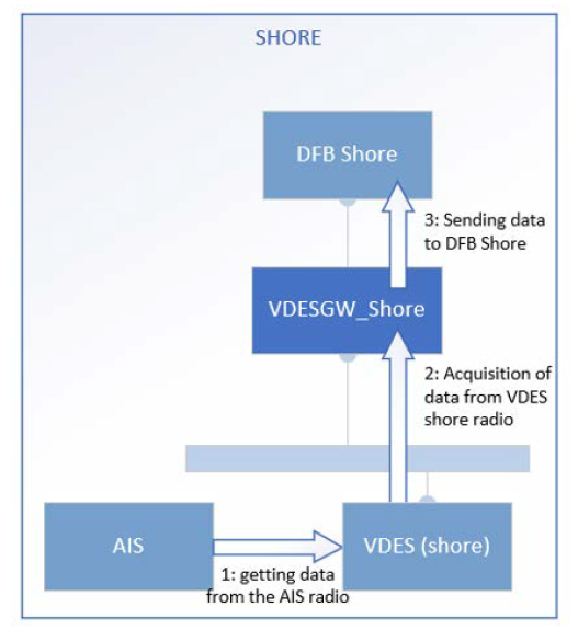
Use Case 1: AIS position extraction
This use case is used as a demonstration of the capability of the VDES shore radio to interface and extract information from the AIS system. The data is provided to VDES_GW which forwards it to Palaemon’s ICT system, called DFB (Data Fusion Bus), at shore: • Step 1: The VDES Shore radio interface the AIS system and extracts the ship position data. • Step 2: The VDES Shore radio publishes the received data in the LAN and the VDES_GW application acquires it. The received data are stored by the application for usage in other scenarios. • Step 3: the VDES_GW application publishes the data to the DFB system.
Figure 5 AIS data extraction use case
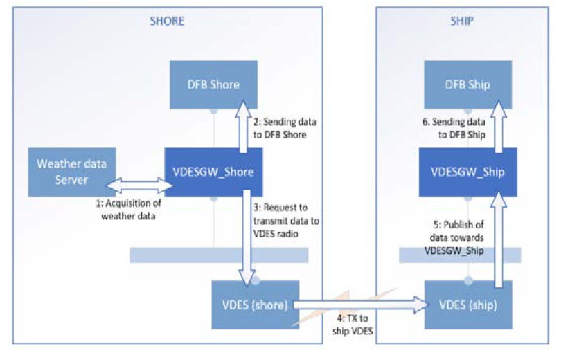
Use Case 2: Weather information acquisition
In this use case the VDES_GW_Shore application polls the Weather data service to get the current forecast of weather condition (next three hours) in the current position of the ship (acquired as from the previous Use Case 1), and sends this weather data directly to DFB shore and, indirectly, to the DFB Ship through the VDES radio channel: • Step 1: If the VDES_GW_Shore application has a valid and fresh position of the ship, obtained from the Use Case 1, it polls periodically the Weather data service to get the current weather condition for that position. • Step 2: The VDES_GW_Shore application sends the weather data to the DFB Shore. • Step 3: The VDES_GW_Shore application sends to the VDES Shore radio the request to send the Weather data to the Ship. • Step 4: The VDES Shore radio sends the data to the VDES Ship radio. • Step 5: The VDES Ship radio publishes the received data towards the VDES_GW_Ship application. • Step 6: the VDES_GW_Ship application sends the weather data to the DFB Ship.
Figure 6 Weather information acquisition use case
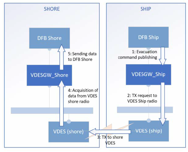
Use Case 3: Evacuation information transmission
This use case demonstrates the transfer of data between Ship and Shore using the VDES radio channel. The “Ship Evacuation command” is used as a sample of data to be transferred: • Step 1: the DFB Ship component publishes an “evacuation command” message; the message is received from the VDES_GW_Ship application. • Step 2: The VDES_GW_Ship application sends to the VDES Ship radio the request to send the evacuation command to the Shore.
• Step 3: The VDES Ship radio sends the data to the VDES Shore radio • Step 4: The VDES Shore radio publishes the received data towards the VDES_GW_Shore application. • Step 5: the VDES_GW_Shore application passes the evacuation command to the DFB Shore application.
Figure 7 Evacuation information transmission use case
ACKNOWLEDGEMENTS
The project “Palaemon” has received funding from the European Union’s Horizon 2020 Research and Innovation Programme under Grant Agreement No 814962.
This website uses cookies so that we can provide you with the best user experience possible. Cookie information is stored in your browser and performs functions such as recognising you when you return to our website and helping our team to understand which sections of the website you find most interesting and useful.
IALA complies with the General Data Protection Regulations of the EU. IALA will include a list of participants with their contact information on the website and in the report of this meeting. Any participant who wishes to remove their contact details from the participants' list should advise the Committee Secretary as soon as possible.
Strictly Necessary Cookies
Strictly Necessary Cookie should be enabled at all times so that we can save your preferences for cookie settings.
If you disable this cookie, we will not be able to save your preferences. This means that every time you visit this website you will need to enable or disable cookies again.
3rd Party Cookies
This website uses Google Analytics to collect anonymous information such as the number of visitors to the site, and the most popular pages.
Keeping this cookie enabled helps us to improve our website.
Please enable Strictly Necessary Cookies first so that we can save your preferences!